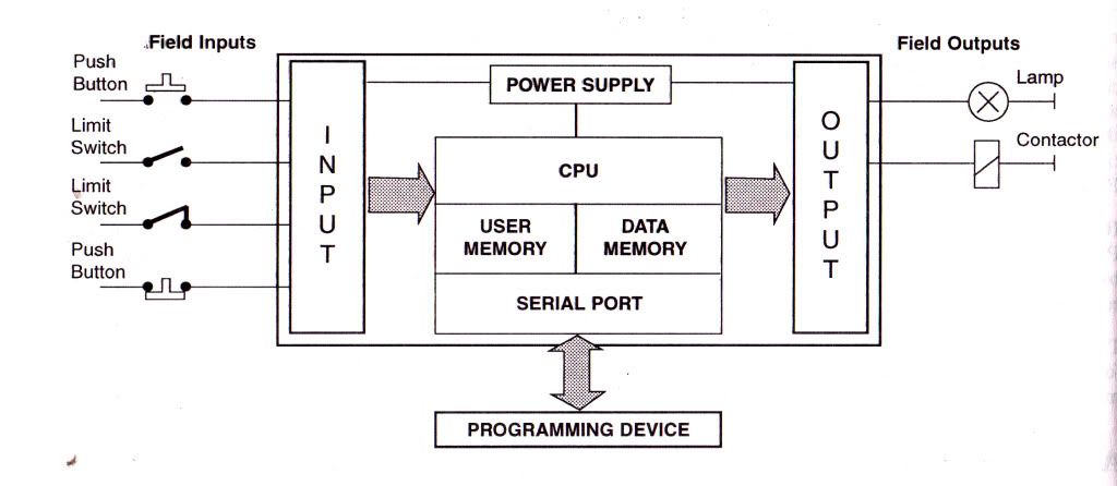
PLC Basic Block Diagram
- A Programmable Controller is a specialized computer. Since it is a computer, it has all the basic component parts that any other computer has; a Central Processing Unit, Memory, Input Interfacing and Output Interfacing. A typical programmable controller block diagram is shown below,
- The Central Processing Unit (CPU) is the control portion of the PLC.
- It interprets the program commands retrieved from memory and acts on those commands.
- In present day PLC's this unit is a microprocessor based system.
- The CPU is housed in the processor module of modularized systems.
- It interprets the program commands retrieved from memory and acts on those commands.
- Memory in the system is generally of two types; ROM and RAM.
1. The ROM memory contains the program information that allows the CPU to interpret and act on the Ladder Logic program stored in the RAM memory.
2. RAM memory is generally kept alive with an on-board battery so that ladder programming is not lost when the system power is removed.
3. This battery can be a standard dry cell or rechargeable nickel-cadmium type.
4. Newer PLC units are now available with Electrically Erasable Programmable Read Only Memory (EEPROM) which does not require a battery.
5. Memory is also housed in the processor module in modular systems.
- Input units can be any of several different types depending on input signals expected as described above.
1. The input section can accept discrete or analog signals of various voltage and current levels.
2. Present day controllers offer discrete signal inputs of both AC and DC voltages from TTL to 250 VDC and from 5 to 250 VAC.
3. Analog input units can accept input levels such as ±10 VDC, ±5 VDC and 4-20 ma. current loop values.
4. Discrete input units present each input to the CPU as a single 1 or 0 while analog input units contain analog to digital conversion circuitry and present the input voltage to the CPU as binary number normalized to the maximum count available from the unit.
5. The number of bits representing the input voltage or current depends upon the resolution of the unit.
6. This number generally contains a defined number of magnitude bits and a sign bit.
7. Register input units present the word input to the CPU as it is received (Binary or BCD).
- Output units operate much the same as the input units with the exception that the unit is either sinking (supplying a ground) or sourcing (providing a voltage) discrete voltages or sourcing analog voltage or current.
1. These output signals are presented as directed by the CPU. The output circuit of discrete units can be transistors for TTL and higher DC voltage or Triacs for AC voltage outputs.
2. For higher current applications and situations where a physical contact closure is required, mechanical relay contacts are available.
3. These higher currents, however, are generally limited to about 2-3 amperes.
4. The analog output units have internal circuitry which performs the digital to analog conversion and generates the variable voltage or current output.
Extending PLC:
- Every PLC controller has a limited number of input/output lines.
- If needed this number can be increased through certain additional modules by system extension through extension lines.
- Each module can contain extension both of input and output lines.
- Also, extension modules can have inputs and outputs of a different nature from those on the PLC controller (ex. in case relay outputs are on a controller, transistor outputs can be on an extension module).


1 comments:
Download PLC Programming Software For Free
Post a Comment